Last week in Athens we integrated the SDK4SDN aka Netfloc in the T-Nova Pilot testbed in order to showcase service function chaining using two endpoints and two VNFs (Virtual Network Functions).
NETwork FLOws for Clouds (Netfloc) is an open source SDK for datacenter network programming developed in the ICCLab SDN initiative. It is comprised of set of tools and libraries that interoperate with the OpenDaylight controller. Netfloc exposes REST API abstractions and Java interfaces for network programmers to enable optimal integration in cloud datacenters and fully SDN-enabled end-to-end management of OpenFlow enabled switches.
The PoP consisted of three OpenStack nodes (Juno), one node reserved for the SDN controller (the SDK) and one physical switch, Figure 1.

Figure 1. Pilot testbed setup used for the SFC
The SDK4SDN has been implemented in Java programming language and it is currently integrated as a holistic component that includes a Lithium release of the OpenDaylight controller. It has been to date tested and supported using OpenStack Kilo (in the ZHAW SDN testbed) and OpenStack Juno (in the Demokritos testbed).
To use SDK4SDN, the network needs to be fully SDN enabled through the OVS switches. The network interfaces of the switch should be connected to all of the other nodes.
Firewall Configuration of Neutron Node
The default SFC implementation requires disabling iptables rules that would prevent non-standard forwarding to OpenStack instances and avoid dropping the packets that are transmitted by Nova instances. Nova-compute was prevented from creating the iptables rules by configuring the Noop driver in the /etc/neutron/plugins/ml2/ml2_conf.ini file on the control and the /etc/nova/nova.conf file in the compute nodes.
Deployment and Installation
The SDK4SDN can only detect OVS topology. A Physical switch that supports OVS is for example the Pica8 switch in OVS mode. The OVS configuration on the compute nodes has to be setup such that the switches are connected in layer 2 domain. For each compute node, an OVS port was configured that bridges the physical interfaces. Note that if a compute host has a single physical interface, then the IPs on that interface need to be attached to the internal interface of the OVS bridge.
The OpenDaylight controller needs to be reachable via ports TCP 6640 and TCP 6633 from every OVS and also reachable via HTTP from an Orchestrator on the Northbound in order to accept the SFC instructions via REST calls.
The steps in order to setup the environment are the following:
- Login to all OpenStack nodes, the switch and ODL node as root
- Download the SDK4SDN form the GitHub page and compile the code using: mvn clean install
- Configure the OVSs on each of the nodes to connect to the IP of the Open Daylight controller as well as set up the ODL as manager on port 6640:
ovs-vsctl set-manager tcp:Controller_IP:6640
ovs-vsctl set-contorller tcp:Controller_IP:6633
With these basic steps the SDK is ready to be started as long as we have the environment prepared for this. To make sure all the state is clear before running the SDK, the following steps and checkups are required:
- OVS running in all of the nodes (run ovs-vsctl show to confirm and also check the configuration of the OVSs)
- SDK not running: ./karaf/target/assembly/bin/status
- Cleanup OpenStack environment (delete all: VMs, router interfaces, routers, and networks)
- Make sure you delete the following directories in the SDN node:
rm -rf karaf/target/assembly/data
rm -rf karaf/target/assembly/journal
rm -rf karaf/target/assembly/snapshots
After the above steps start the SDN controller (the SDK): ./karaf/target/assembly/bin/start.
To monitor the logs on the SDN node run: tail -f ./karaf/target/assembly/data/log/karaf.log.
It displays the initialization process and the link discovery. The SDK startup is done when the last log message from ODL displays: GraphListener. Next, the basic networking environment has to be created: public network that connects via router to all the private networks that are designated for the endpoint instances (sender & receiver) and the VNFs.
While creating the network elements in OpenStack, the SDK log displays how the neutron ports get detected and few seconds later, the same for the ovs ports. After that, the paths get detected and flows are pushed to the br-int of the controller. On the controller you can check the created ports and the flows: ovs-vsctl show; ovs-ofctl dump-flows br-int.
Service Function Chaining
Create two VMs: sender and receiver VM with for ex. CentOS image and tiny flavor, connecting them to the internal private network. Create one VM destined for the dummy VNF (it can be created form snapshot dummy_vnf or simple Ubuntu image with OVS installed). Create another VM for the vTC VNF. After inserting the private keys, connect the VMs to the private network. In the control node, create four neutron ports vnf1_in, vnf1_out, vnf2_in, vnf2_out and attach them to both the dummy VNF and the vTC VNF:
neutron port-create vnf_in
neutron port-create vnf_out
nova interface-attach --port-id [PORT_ID_vnf_in] vnf
nova interface-attach --port-id [PORT_ID_vnf_out] vnf
The SDK log displays the addition of the new paths triggered by the creation of the VMs. At this point the broadcast and path flows get created, Figure 2. To check this, go to the node where a VM is spawned, and ovs-vsctl show to see the flows installed. Besides the NORMAL and the LLDP flows, you can see other flows: broadcast flows to the Router, the DHCP and the other VMs; flows for connections between the VMs, etc.
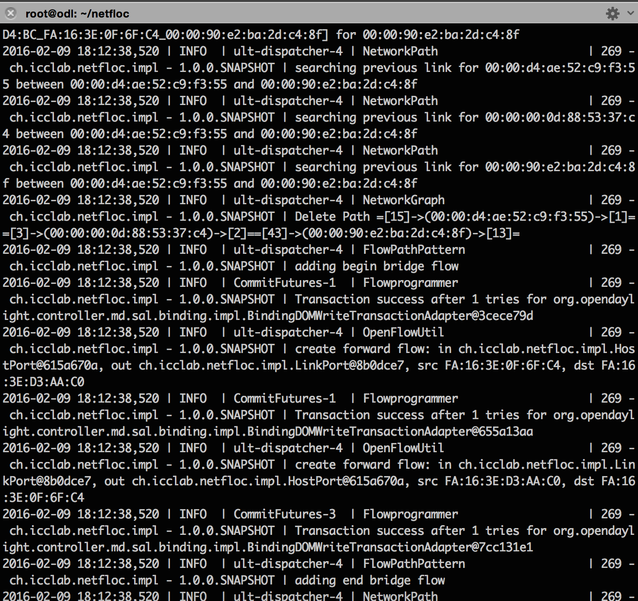
Figure 2. Netfloc log display: network path, graph, and bridge detection
After the VNF has the two interfaces assigned from the other two private networks, associate a floating IP and access the VNFs. Meanwhile login via the console to the sender VM and ping the receiver VM to confirm connectivity. The dummy VNF represents a simplistic case of the T-Nova vTC VNF (Virtual traffic classifier). For this demo we used the vTC as a second VNF. The idea behind the basic functionality of this VNF is to steer traffic from one interface to another (ex. eth1 to eth2) and display the packets per second. More details on this VNF can be found here.
Next step is to call the REST APIs via cURL in the command line of the ODL node in order to invoke the creation of the chain. For the API call, the neutron port IDs of the VMs need to be specified in order [“sender, vnf1_in, vnf1_out, vnf2_in, vnf2_out, receiver”] as a string of comma separated values. To retrieve the Neutron ports of the VMs, run on the controller: neutron ports-list and match the port-id with the IPs of both, the endpoints and the VNFs. The POST API call looks as shown below:
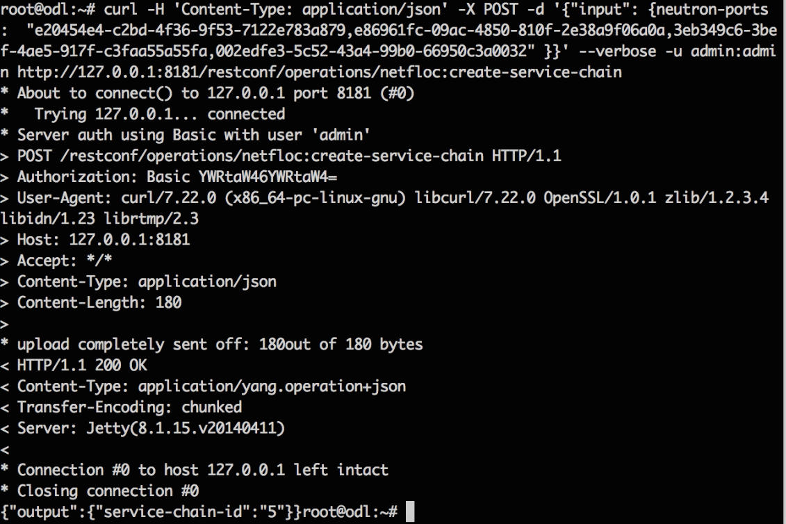
Figure 3. SFC Create request
After correct chain establishment, there is 200 OK response message form the SDK and on the sender console it is no longer detected the ping communication between the sender and the receiver. This shows that there is intermediate node(s) (the dummy_vnf and the vTC) blocking the ping, which confirms a traffic redirection from the initial path. In order to get the traffic through, the following flow has to be added in the dummy VNF:
ovs-ofctl add-flow [vnf_br] in_port=1,actions=output:2Make sure of the correct mapping between the input and output ports and also that the two ports eth1 and eth2 are properly listed in the: ovs-ofctl dump-ports-desc [vnf_br]. After seting up the first VNF in the chain, the following command connects the interfaces in the vTC VNF the same way for the dummy VNF:
vtc/PF_RING/userland/examples/pfbridge -a eth1 -b eth2Having all set, confirm that the ping goes through again. This can be also checked by running: tcpdump –i eth1 /eth2 on the node where the VNFs are running and checking for ICMP messages, as the left terminal on the Figure 4 shows.
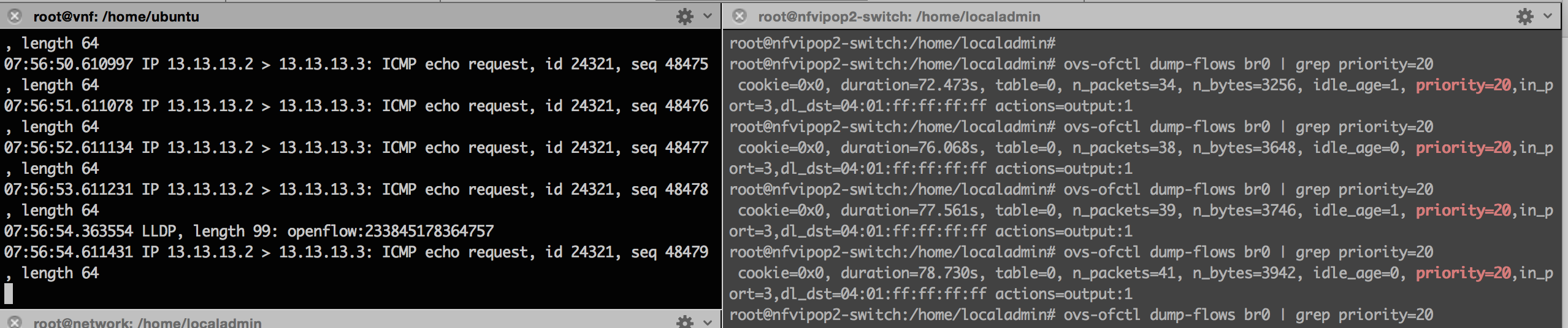
Figure 4. ICMP messages in the dummy VNF (left) and SFC flows on the switch (right)
Run on the switch (or the hosts where the VNF VMs are installed) terminal: ovs-vsctl dump-flows [br_name] to see that the packets_in counter increases as the pinging proceeds (for the flows with priority=20, i.e. the chain flows, as the right Figure 4 shows). Delete the flow in the VNF in order to see that the ping stops: ovs-ofctl del-flows vnf.
To delete the chain, a POST call is made using the service-chain-id as input parameter in the JSON string, Figure 5:

Figure 5. SFC delete request
In conclusion, we can apply the same technique using any other VNF as long as the Neutron port IDs of the VNF VMs are passed in the REST call to the SDK. Finally here is the video of the chaining process.