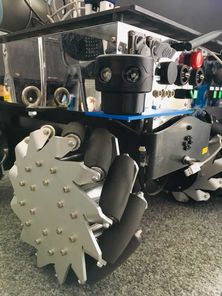
Our lab has acquired a new robot as part of its ROS based robotic fleet. We opted with the SUMMIT-XL Steel from Robotnik; a behemoth compared to our much-loved TurtleBots.

The first vital step for any mobile robot is to setup the ROS navigation stack: the piece of software that gives the robot the ability to autonomously navigate through an environment using data from different sensors.
A major component of the stack is the ROS node move_base which provides implementation for the costmaps and planners. A costmap is a grid map where each cell is assigned a specific value or cost: higher costs indicate a smaller distance between the robot and an obstacle. Path-finding is done by a planner which uses a series of different algorithms to find the shortest path while avoiding obstacles. Optimization of autonomous driving at close proximity is done by the local costmap and local planner whereas the full path is optimized by the global costmap and global planner. Together these components find the most optimized path given a navigational goal in the real world.
Most of the configuration process is spent tuning parameters in YAML files; however, this process is time consuming and possibly frustrating if a structured approach is not taken and time is not spent reading into details of how the stack works. Many helpful tuning guides are already available: Basic Navigation Tuning Guide and ROS Navigation Tuning Guide to name a few (we encourage anyone new to the stack to thoroughly read these). Hence, this post will aim to give solutions to some less-discussed-problems.
Configuring a 2-LIDAR setup
To give the robot a full 360 degree view of its surroundings we initially mounted two Scanse Sweep LIDARs on 3D-printed mounts. One of them recently broke and was replaced with a LDS-01 laser scanner from one of our TurtleBot3s. Each laser scanner provides 270 degrees of range data as shown in the diagram below. Apart from the LIDARs, the robot came equipped with a front depth camera.

)
The biggest challenge in setting up our own LIDARs was aligning all three range sensors: front orbbec astra pro 3d camera, front LIDAR, and rear LIDAR. The key here is to make precise coordinate measurements of the mounted laser scanner with respect to the origin of the robot i.e. the base_link frame.
Merging laser scans
Both AMCL and GMapping require as input a single LaserScan type message with a single frame which is problematic with a 2-LIDAR setup such as ours.
To solve this issue we used the laserscan_multi_merger node from ira_laser_tools to merge the LaserScan topics to scan_combined and to the frame base_link. The relay ROS node would be insufficient for this issue since it just creates a topic that alternately publishes messages from both incoming LaserScan messages.
Note there is a known bug with the laserscan_multi_merger node which sometimes prevents it from subscribing to the specified topics when the node is brought up at the same time as the LIDARs (i.e. same launch file). A simple fix we found is to use the ROS package timed_roslaunch which can delay the bring-up of the laserscan_multi_merger node by a configurable time interval.
Clearing 2D obstacle layer (ObstacleLayer) on costmap
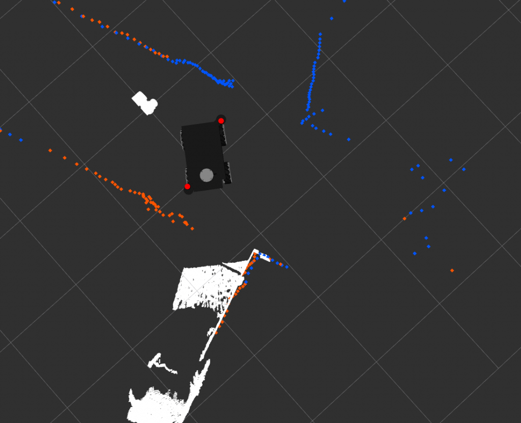
“Ghost obstacles” (as the online community likes to call them) are points on the costmap that indicate no-longer-existing obstacles. This issue was seen with the Scanse Sweep LIDARs and is prevalent among cheaper laser scanners. Many possible reasons exist as to why this occurs, although the most probable cause has to do with the costmap parameter raytrace_range (definition provided below) and the max_range of the LIDAR.
raytrace_range –The maximum range in meters at which to raytrace out obstacles from the map using sensor data.
source – http://wiki.ros.org/costmap_2d/hydro/obstacles
Here’s a simple example to clarify the issue at hand. An obstacle appears in the line of sight of the laser scanner and is marked on the costmap at a distance of 2 meters. The obstacle then disappears and the laser scanner returns a distance of 6 meters at the original radial position of the obstacle. Ray tracing, which is set to a max distance of 3 meters, is unable to clear these points and thus the costmap now contains ghost obstacles. From this example it is clear the parameter raytrace_range needs to be set to a slightly higher value than the maximum valid measurement returned by the laser scanner.
If the issue persists, the following are a few other costmap parameters worth looking into:
Inf_is_valid = truethis should be set for sensors that return inf for invalid measurements- Specify an observation source to be solely for clearing and solely for marking: e.g.
clearing = true; marking = false always_send_full_costmap = true
Clearing 3D obstacle layer (VoxelLayer) on costmap
Contrary to the obstacle layer discussed above which does 2D obstacle tracking, the voxel layer is a separate plugin which tracks obstacles in 3D. Data is used from sensors that publish messages of type PointCloud; in our case this is our front depth camera.
A similar issue of clearing costmaps was observed with the voxel layer. Specifically, the problem was observed to be hovering around the camera’s blind spot. Two solutions were implemented in order to mitigate this issue.
#1 Clearing costmap using recovery behavior:
Recovery behavior was setup such that it clears the obstacle_3d_layer whenever the planner fails to find a plan. Note recovery behavior only gets executed if a navigational goal is sent so clearing from this solution can only be possible while a goal is trying to be reached. Below are the parameters required for the fix and screenshots of the solution working as intended in simulation.
global_costmap_params_map.yaml/local_costmap_params.yaml
plugins:
     - {name: obstacle_3d_layer, type: "costmap_2d::VoxelLayer"}
     - {name: obstacle_2d_layer, type: "costmap_2d::ObstacleLayer"}
costmap_common_params.yaml
obstacle_3d_layer:
<Hidden parameters>
obstacle_2d_layer:
<Hidden parameters>
move_base_params.yaml
recovery_behavior_enabled: true
recovery_behaviors:
  - name: 'aggressive_reset'
    type: 'clear_costmap_recovery/ClearCostmapRecovery'

aggressive_reset:
  reset_distance: 0.0
layer_names: ["obstacle_3d_layer"]#2 Replacing default Voxel Layer plugin with Spatio-Temporal Voxel Layer:
To further alleviate this issue, specifically when the planner does indeed find a valid plan, the Spatio-Temporal Voxel Layer was implemented to replace the default Voxel Layer costmap plugin. This improved voxel grid package has a voxel_decay parameter which clears 3D obstacles on the costmap progressively with time eliminating the issue completely if voxel_decay is set to 0 seconds (though not entirely favorable when there is no rear depth camera).
Closing Thoughts and Next Steps
The ROS Navigation Stack is simple to implement regardless of the robot platform and can be highly effective if dedicated time is spent tuning parameters. Issues with the stack will depend on the type of mobile platform and the quality/type of range sensors used. We hope this blog has provided new insight into solving some of these issues.
In the future we aim to extend the SUMMIT’s navigational capabilities to using 3D LIDARs or an additional depth camera to give a full 3D view of the environment, web access to navigational control, and real-time updating of a centralized map server.
Nice overview and good tips for ROS users. We made our own diff drive robot based on Arlo Robot platform. However, the steps to tuning the amcl parameters is very simples but required time and tests. As you said, I will try to implement the raytrace range with a slightly value.
Hello,
I am currently working with the same robot: Summi-xl-steel, I am also having the problem with merging both lasers, it seems like ira_laser_tools node for merging them it’s buggy and doesn’t subscribe when launching it at the same time as the rest of the robot. I managed to fix this with the timed_roslaunch package but the problem comes when launching also the gmapping node, I can’t make it to work due to the roslaunch delay:
– If I don’t use the delay for the merge node the gmapping node doesn’t work because nothing it’s is published in the new /merge_lasers topic since the node it is not subscribing to the original laser topics due to the bug.
– If I do use the delay (above 3 seconds to work in my case) then the gmapping crashes because it starts before the merge_node and requests a topic which has not been created yet (/merge_lasers) .
I have tried lots of different possibilities but nothing seems to work.
How did you manage to solve this problem if you had to face it?
Cheers,
Andrés