In the previous article we defined use cases for an OpenStack implementation according to the usage scenario in which the OpenStack environment is deployed. In this part of the Dependability Modeling article series we will show how these use cases relate to functions and services provided by the OpenStack environment and create a set of dependabilities between use cases, functions, services and system components. From this set we will draw the dependency graph and make the impact of component outages computable.
Construct dependency table
The dependency graph can be constructed if we define which functions, services and components allow provision of a use case. In the example below (Fig. 1) we defined the system architecture components, services and functions which allow to create, delete or update details of a Telco Account (account of mobile end user). Since these operations are provided within virtual machines, VM User Management and VM Security Management functions provide availability of this use case. Therefore we draw a column which contains these functions. Because these functions need a User Management, SSH & Password Management service in each VM in order to operate, we draw a second column which contains the required services. Another column is constructed which tells the system components required in order to deliver the required services.

The procedure mentioned above is repeated for all use cases. As a result you get a table like the one in (Tab. 1). This dependency table is the starting point for the production of the dependency graph.

Construct dependency graph
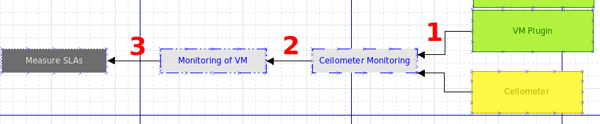
For each component that is listed in the table you have to model the corresponding services, functions and use cases. This is performed like in the example in (Fig. 2). We start from the right of the graph with the Ceilometer component and the VM plugin and look which services are provided by those components: it is e. g. the “Ceilometer Monitoring” service. Therefore we draw an icon that represents this service and draw arrows from the Ceilometer and VM plugin components to the service icon (1). In the next step we look which function is provided by the Ceilometer Monitoring service. This is the “Monitoring of VM” function. Therefore we paste an icon for the function and draw an arrow to this function (2). Then we look for the use cases provided by the Monitoring of VM function. Since this is e. g. “Measure SLAs”, we paste an icon for this use case and draw another arrow to “Measure SLAs” (3). The first path between an use case and components on which it depends is drawn. This procedure is repeated on all components in (Tab. 1).
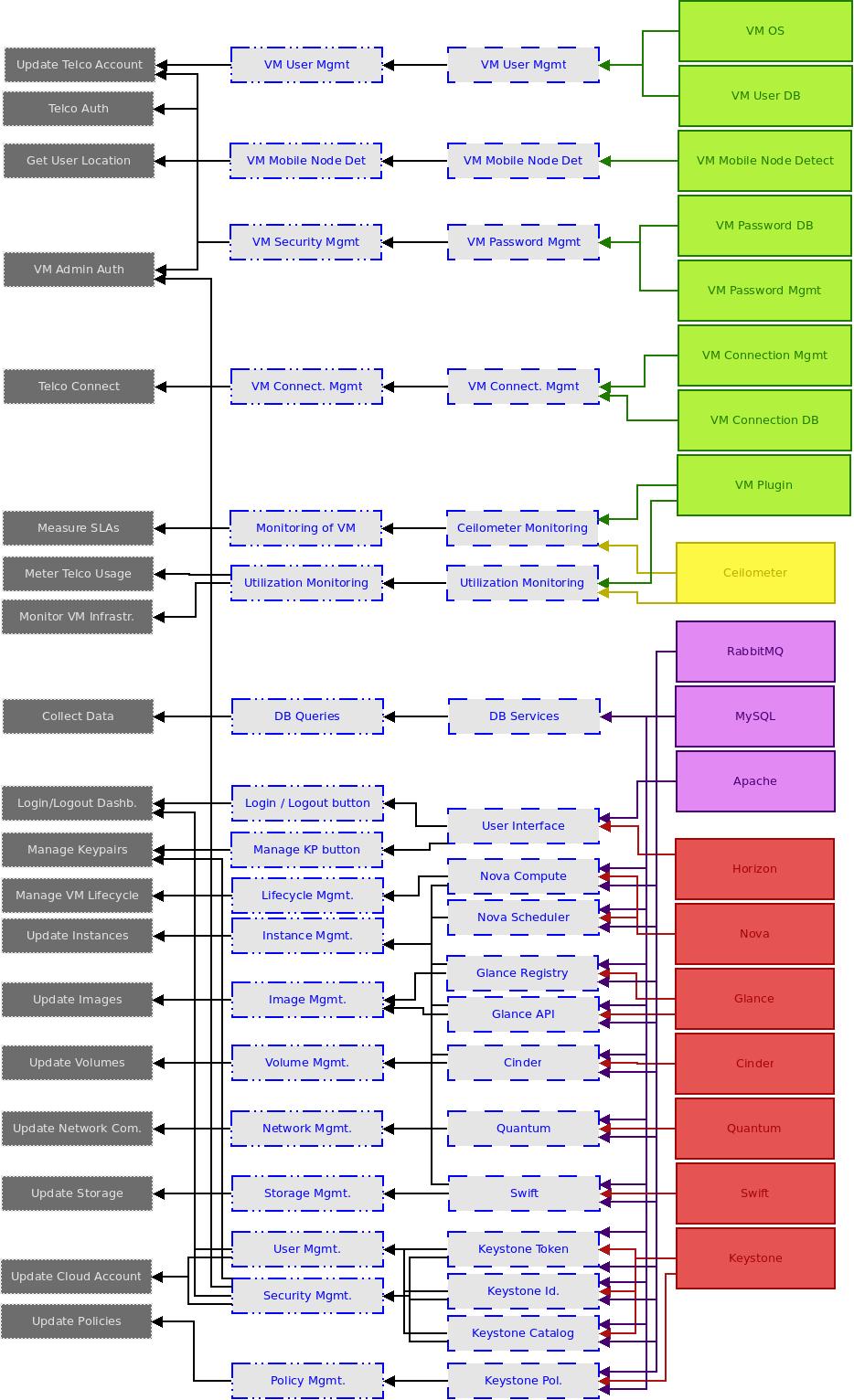
The result is the dependency graph shown below (Fig. 3).
Add weight factors to use cases
Once the dependency graph is constructed, we can calculate the “impact” of component outages. When a component fails, you can simply follow the arrows in the dependency graph to see which user interactions (use cases) stop to be available for end users. If e. g. the Ceilometer component fails, you would not be able to measure SLAs, meter usage of Telco services or monitor the VM infrastructure.
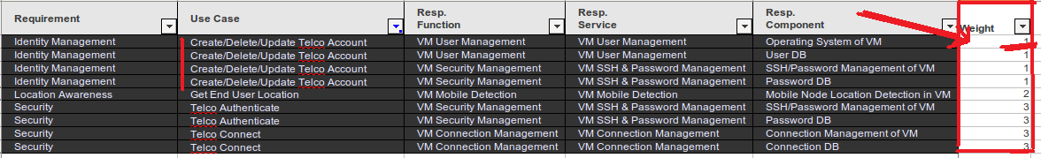
But it would not be a very sophisticated practice to say that each use case is equally important to the end user. Some user interactions like e. g. creation of new VM nodes need not be available all the time (or at least it depends on the OLAs of the Telco). Other actions like e. g. Telco authentication must be available all the time. Therefore, we have to add weight factors to use cases. This can be done by adding another column to the dependency table and name it “Weight factor”. The weight factor should be a score measuring the “importance” of an user interaction in terms of business need. In a productive OpenStack environment, financial values (which correspond to the business value of the user interaction) could be assigned as weight factors to each use case. For reasons of simplicity we take the ordinal values 1, 2 and 3 as weight factors (whereby 1 signifies the least important user transaction and 3 the most important user transaction). For each use case row in the dependency table we add the corresponding weight factor (Fig. 4).
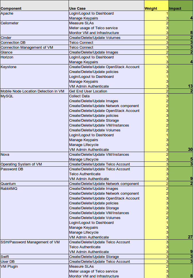
As a next step, we create a pivot table containing the components and use cases as consecutive row fields and the weight factors as data field. In order to avoid duplicate counts (of use cases) we use the maximum function instead of the sum function. As a result we get the pivot table in (Tab. 2).
Calculate outage impacts
Calculation of system component outages is now quite straightforward. Just look at the pivot table and calculate the pivot sum of the weight factors of each component. As a result we have a table of failure impact sizes (Tab.3).
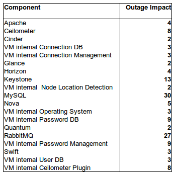
This table reveals which components are very important for the overall reliability of the OpenStack environment and which are not. It is an operationalization of the measurement of “failure impact” for a given IT environment (failure impacts can be measured as number). The advantage of this approach is that we can build a test framework for OpenStack availability based on the failure impact sizes.
Most obviously components whith strong support functionality like e. g. MySQL or the Keystone component have high failure impact sizes and should be strongly protected against outages. VM internal components seem to be not so important because VMs can be easily cloned and recovered in a cloud environment.
In a further article we will show how availability can be tested with the given failure impact size values on a given OpenStack architecture.
1 Kommentar