Power over Coax FPD-Link III Link Streaming Adapter for Raspberry PI CSI-Interface
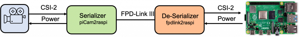
The Institute of Embedded Systems at ZHAW has developed an open source adapter which allows streaming of a CSI-2 Camera interface to a Raspberry Pi. This allows connecting cameras with CSI interface via a long distance cable (up to 15m) to the CSI-2 input of a Raspberry Pi. The long range adapter uses FPD-Link III […]