A computer with a GPU combined with an FPGA is a powerful tool for high speed video processing. An FPGA can preprocess multiple video streams in realtime and then send the data to the GPU for further processing.
FPD-Link III is a cost-effective solution for high speed video transmission. It has made a name for itself for its widespread use in the automotive industry. The transmission can be done over a simple coaxial cable but includes not just a video data stream, but also a bidirectional configuration channel and a power supply for the camera.
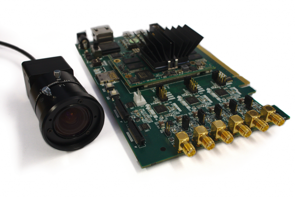
The purpose of this project is to design hardware which makes it possible to take full advantage of the developed FPGA-GPU co design [1] and to combine it with an FPD-Link III interface. The resulting baseboard utilizes PCI Express implemented in an FPGA which allows connecting up to 6 FPD-Link III. The FPGA is embedded in a system-on-chip and could potentially also be used stand-alone. As a further video source option, it also includes two connectors for MIPI CSI cameras. These are designed to be compatible with RaspberryPi cameras.
[1] See our blog “Direct communication between FPGA and GPU using Frame Based DMA (FDMA)” for solving the bottleneck between CPU and GPU
Motivation
In a standard computer, PCI Express (PCIe) offers the possibility for two devices to exchange data on up to 16 high speed data lanes. The CPU is master of the PCIe interface and therefore usually initiates data transfers. This causes overhead and limits the maximum transfer speed for certain applications. The paper FPGA-GPU Codesign from xxx implements solutions to transfer data directly from an FPGA over PCIe to a GPU without the CPU being a bottleneck for the data througput. This approach can be especially useful for applications with high resolution video streams which need to be processed in real time. Live video streams from multiple cameras can be preprocessed in the FPGA and then be transmitted via PCI Express to the GPU for further processing. This thesis is about implementing hardware suitable to take full advantage of this idea.
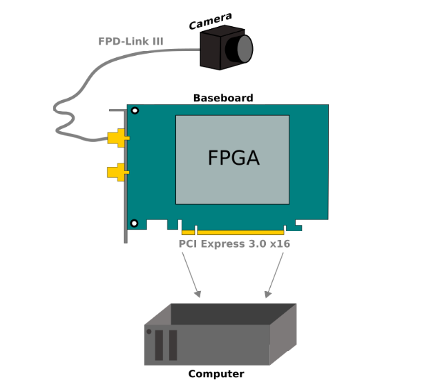
The goal is to be able to connect multiple cameras to a computer via a PCIe baseboard with an FPGA. The camera interface chosen for this baseboard is FPD-Link III.
FPD-Link III
FPD-Link III is a cost-effective solution for high speed video transmission. It has gained relevance in automotive applications. Cameras in cars are becoming more common. Nowadays even low cost cars come with a rear camera to assist while parking. FPD-Link III can also be used in different industrial applications, especially for real time use-cases which require high-bandwidth transmissions.
The goal of this project is to develop a Baseboard that makes it possible to connect multiple FPD-Link III cameras to a standard computer with high data rates. The video data from the cameras should be preprocessed in the FPGA and then be forwarded to the computer via PCI Express. Cameras also require to be configured. This configuration will be handled in the FPGA over FPD-Link III.
The Basics of FPD-Link III
Flat panel display link III (FPD-Link III) can be used to receive data from a camera or to send data to a display. The well known standards for high speed video transmission on the consumer market are HDMI, DisplayPort and USB. However, these cables are expensive and better suited for short distances. FPD-Link III can be used with coaxial or a shielded twisted-pair (STP) cables. A 15 m coaxial cable supports data rates up to 6 Gbps and a 10 m long STQ (shielded twisted quad) cable supports up to about 5 Gbps. But FPD-Link III does not only transmit video data. In addition to the video channel, there is also a bidirectional control channel. This is needed for a processor to configure the camera sensor. In case of a display, the control channel can for example be used to send commands from the touchscreen to the processor. The video channel occupies the frequency range between 70MHz and 700MHz whereas the control channel lies between 1MHz and 5MHz.
An additional feature of FPD-Link III is Power over coax which offers the possibility to power the image sensor over the coax cable. This eliminates the need for a further cable for power supply.
FPD-Link III to PCIe Video Pipeline
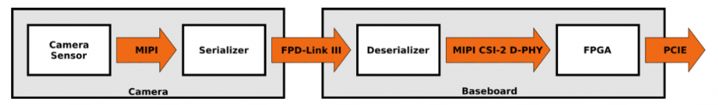
As shown in the figure below, the video is transmitted from a camera sensor to a serializer which sends the video over FPD-Link III in a coaxial cable to the deserializer. The deserializer transmits the data to the FPGA over MIPI CSI-2 D-PHY. In the FPGA, the data can be preprocessed and then be sent over PCIe to the memory on the computer. There will be multiple deserializers on the baseboard so multiple cameras can be connected.
The concept of the Baseboard
The following figure shows a sketch of the concept for the baseboard. The path of the video data is colored in bright green. On the left side there are six coax connectors for the FPD-Link III interface (number of coax connectors is limited to six because of the defined maximum width of a PCIe card). The data goes through the deserializer to the FPGA. From the FPGA the data is transmitted to a computer over PCIe. In addition to the FPD-Link III connectors there are two MIPI CSI-2 D-PHY connectors which are compatable with the RaspberryPi-Camera. This gives the user an additional option for a video source.
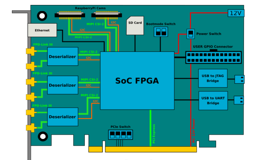
The main focus of the project is the deserializer for FPD-Link III, the integration of a SoC FPGA and the PCIe interface. The company Enclustra offers a selection of SoC modules which entail a Xilinx MPSoC (Multiprocessor system-on-chip), SDRAM, flash memory and more. The module can be mounted to the baseboard via connectors. The figure above shows additional hardware and interfaces which are needed for an operating baseboard. The SoC needs a JTAG interface for programming and debugging. An SD-card slot is added and can be used as the boot device. The boot mode switch can be used to change the source device for the boot process. The SoC can be reset over a button and a status LED gives further information about the state of the SoC. The UART (Universal Asynchronous Receiver Transmitter) is needed for the console output of the processor. An ethernet connector makes it possible to get access to the processor with SSH (Secure Shell).
A power switch makes it possible to choose between an external power supply or the 12V supplied over the PCIe interface from the computer. The external supply is needed when the SoC should be programmed before the computer is booted. The connection to PCIe devices are established while booting in the bios, which means the FPGA should be programmed before the computer turns on. The external supply is also useful when the board consumes more power than the computer can supply.
PCIe can be used in four different lane configurations: 1-, 4-, 8- or 16-lanes. The PCIe switch is used to choose between these options.
FPD-Link III DeSerializer
The deserializer converts the FPD-Link III signal to MIPI CSI-2 which can be connected to the FPGA. Texas Instruments (TI) offers a variety of solutions for FPD-Link III serializers and deserializers. The requirements for choosing a deserializer are the following:
• Input: FPD-Link III LVDS
• Output: MIPI CSI-2
• Able to connect to 2+MP (mega pixel) cameras
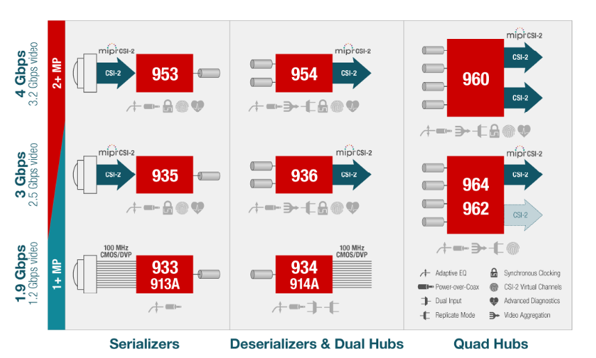
TI provides two deserializers which meet the given requirements. These are DS90UB960-Q1 (960) and DS90UB954-Q1 (954).
The 960 and 954 models have the same maximum data rates for FPD-Link III and MIPI CSI-2. However, 954 has more GPIO pins per camera. 954 has 7 GPIOs for 2 cameras and 960 has 8 GPIOs for 4 cameras. GPIO signals are useful to get diagnostics of the deserializer, but they can also be used to connect directly to the camera sensor board. Some cameras need for example an enable signal which can be set by the processor over these GPIOs. The deserializer chosen for this baseboard is the DS90UB954-Q1.
Below picture shows the available serializers and deserializers from TI
Implementation of the Deserializer
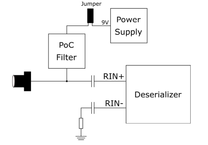
The DS90UB954-Q1 deserializer can be used with one or two camera sensors over FPD-Link III. It supports 2MP@60fps and 4MP@40fps cameras. The two input channels RIN0/RIN1 can be enabled and disabled through registers of the deserializer (Register: RX_PORT_CTL, 0x0C). The input channels can be used as single ended (coaxial channel) or as differential (STP). This baseboard uses single ended coaxial connections. This means the RN- port of a channel is connected to ground with a 15nF-capacitor and a 50 ohm resistor. The RN+ port is connected to the conductor inside the coax connector with a 33nF capacitor in series. This capacitor blocks the receiver ports of the deserializer from any DC voltage. This is especially important if power over coax is used.
Power over coax (PoC) makes it possible to use the coaxial cable to supply power to the camera sensor. The output of a power supply is connected to the coaxial connector with a filter in series. This filter is needed to shield the power supply from the AC signal transmitted between deserializer and camera sensor over FPD-Link III.
Typically, the PoC voltage is between 5V and 36V baseboard. Before connecting a camera to the baseboard it must always be checked what PoC voltage is tolerated by the camera board. If needed, the PoC voltage can be cut off from the coax connector design provided from TI.
The FPD-Link III PCIe baseboard was successfully designed and produced. Parts of the baseboard are tested and verify that the baseboard as such is functional. The components for the MPSoC are working properly and the baseboard was successfully detected over PCIe. Some tests showed that there is still work to do in the bring-up of the baseboard.
A task that is still open is the debugging of the PCIe to get a working link with lane width of 8 and 16. The link to a PCIe device is established during the boot of the BIOS (basic input/output system) which is demanding to debug.
Conclusion
Once all these individual parts are completed, they can to be combined into one single system that collects video streams from multiple cameras and transfers the data to a computer via PCIe.